

🔧 MCP Verification Board
📏 Dimensions (unit: mm)
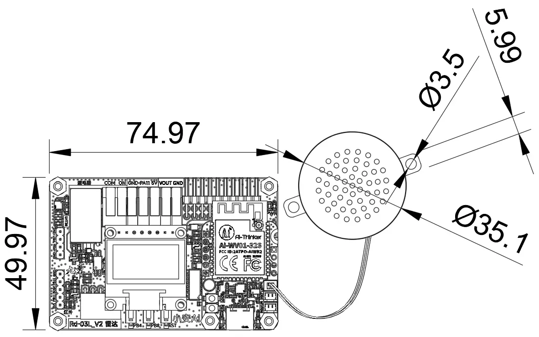
Verification Board PCB Dimension Diagram
🗺️ Resource Block Diagram
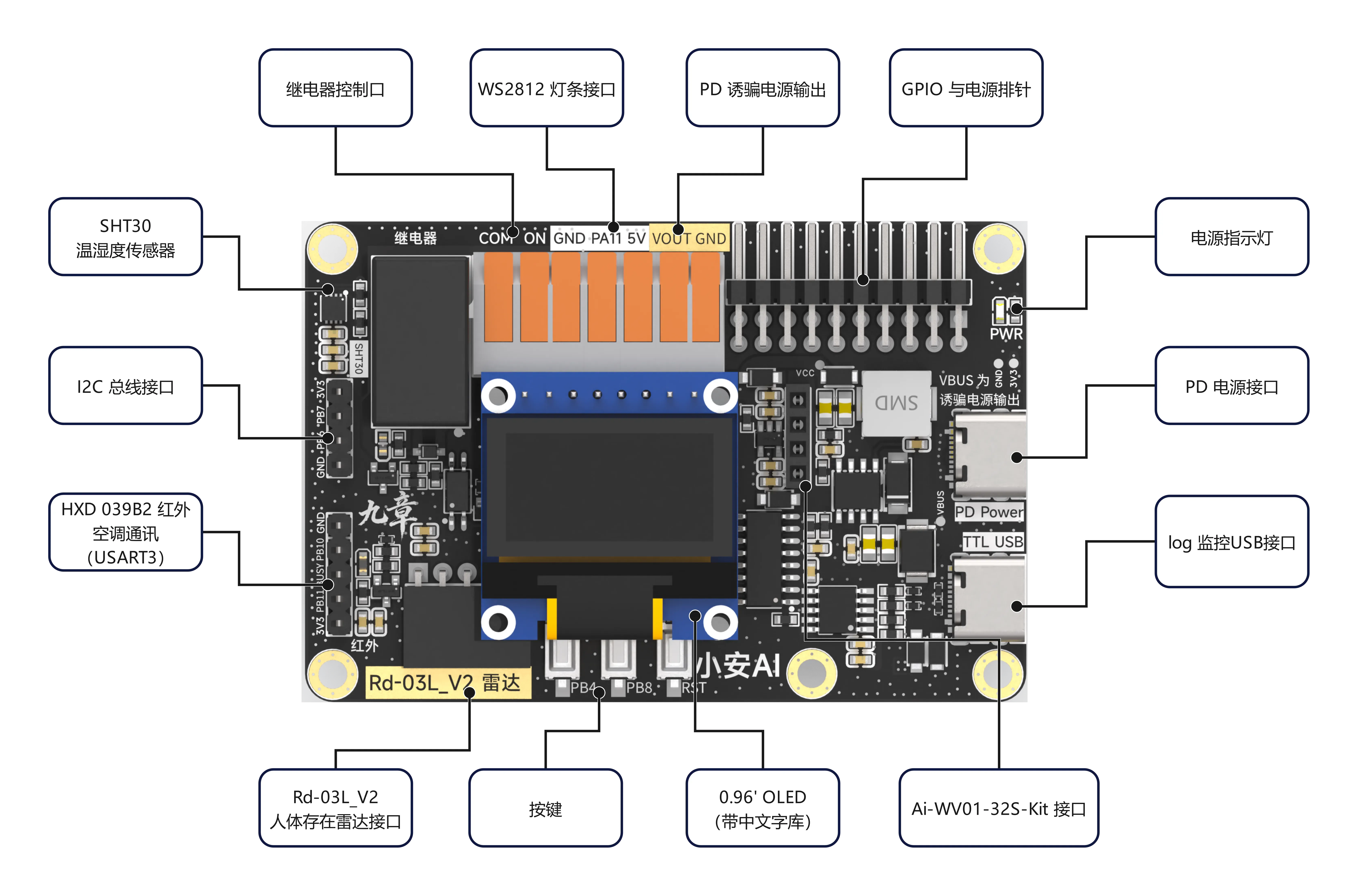
System Architecture and Module Connections
⚙️ Onboard Resources
| Resource | Specification/Model | Description |
|---|---|---|
| 🔌 Relay Control Port | 1-channel NO | Active high / AC 250V 10A, blue indicator LED |
| 🌈 WS2812 LED Strip Interface | Single-wire Serial (PWM DMA) | Single GPIO control, cascade expandable |
| ⚡ PD Decoy Power Output | VBUS Output | I²C controlled output, supports 5V~20V 3A |
| 📍 GPIO & Power Headers | 2.54mm Pin Headers | Reserved ADC/PWM/UART/I²C/SPI |
| 💡 Power Indicator LED | PWR LED | Power status indication (red) |
| 🔋 PD Power Interface | Type-C USB-C | PD decoy power input |
| 💻 Log Monitor USB Port | TTL UART | Debug log output, 1500000 bps (switch to 921600 if unstable) |
| 🌡️ SHT30 Temp/Humidity Sensor | SHT30/SHT31 | I²C interface, ±0.2°C / ±2%RH |
| 🔗 I²C Bus Interface | SDA / SCL | External I²C device expansion port |
| 📺 HXD 039B2 IR AC Communication [Reserved] | USART3 | IR transmission; firmware in development |
| 📡 Rd-03L_V2 Radar Interface [Reserved] | 24GHz mmWave | Human presence detection; firmware in development |
| 🔘 Buttons | PB4/PB8/RST | Button input / Reset button |
| 🖥️ 0.96" OLED | SSD1306 (128×64) + GT20L61S | SPI interface, onboard Chinese font chip |
| 🤖 Ai-WV01-32S-Kit Interface | BL602 + VB6824 | Core AI voice development board |
🔌 GPIO Pin Allocation Details
The 9Mod MCPBoard is based on STM32F103CBT6. Each functional module is connected to the MCU via jumper caps/headers, supporting flexible pin allocation and level isolation. Below is the complete GPIO usage description:
🤖 Ai-WV01-32S-Kit
Ai-WV01-32S-Kit is a Mini development board centered around the Ai-WV01-32S module.
Ai-WV01-32S is a compact voice interaction module (built-in BL602 + VB6824) designed by Ai-Thinker Technology that connects to the XiaoZhi AI Agent. It is powered by BL602 and VB6824 chips, designed for lightweight smart voice scenarios. It features high integration, high cost-effectiveness, offline voice wake-up, and voice interruption capabilities, suitable for AI voice products, audio/video multimedia, IoT, smart home, etc.
- SMD-40 package
- IEEE 802.11 b/g/n
- 20 MHz bandwidth, max 72.2 Mbps
- Bluetooth Low Energy 5.0, Bluetooth Mesh
- Station + BLE mode, Station + SoftAP + BLE mode
- 32-bit RISC CPU, 276KB RAM
- SDIO, SPI, UART, I²C, IR remote, PWM, ADC, DAC, PIR, GPIO
- QSPI/SPI Flash on-the-fly AES decryption (OTFAD), AES 128 CTR mode
- AES 128/192/256-bit encryption engine
- Background noise suppression
- Voice recognition (ASR) algorithm
- Voice noise reduction algorithm
- Multiple sleep modes, deep sleep
- Supports secondary development with Windows/Linux environments
📏 Dimensions (unit: mm)
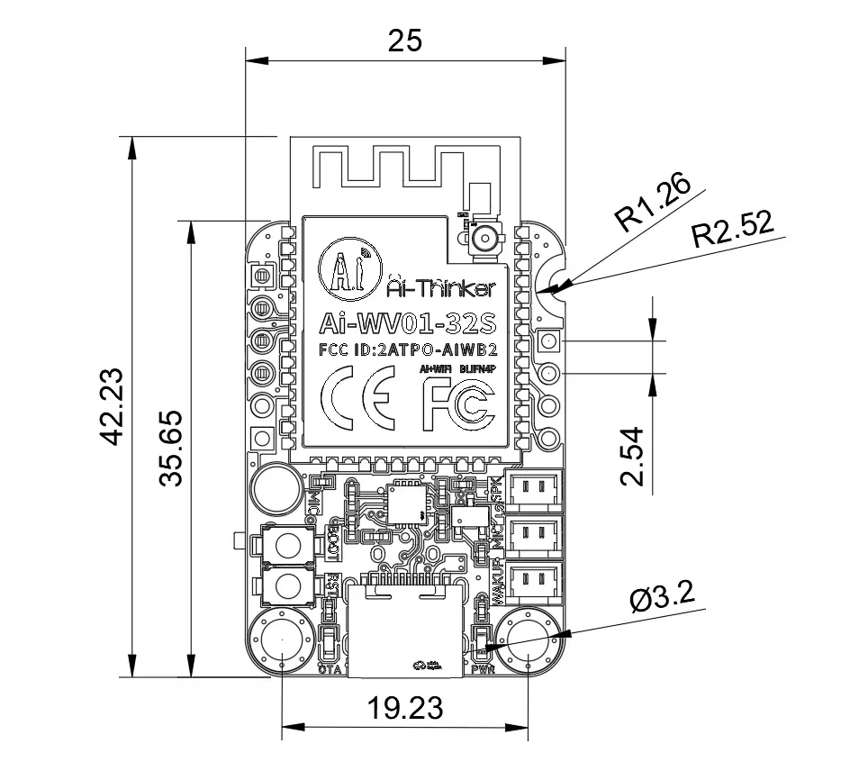
Ai-WV01-32S-Kit Development Board Dimension Diagram
🗺️ Resource Block Diagram
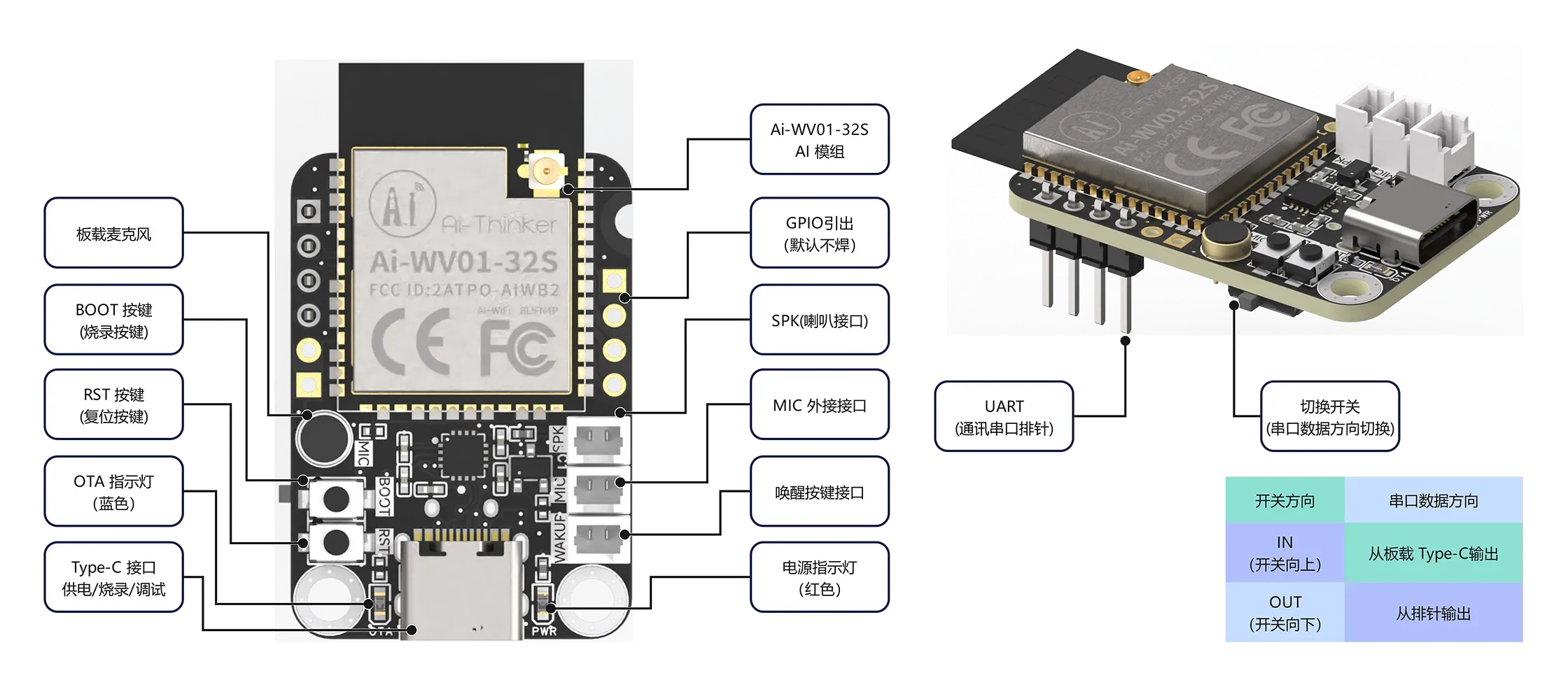
Module Internal Functional Block Diagram
🧠 AI Agent
Ai-WV01-32S-Kit is an officially licensed XiaoZhi AI development board. It uses the standard AI agent to control hardware by forwarding MCP commands:
- Natural Language Understanding — Supports Chinese/English dialogue, understands user intent
- Tool Calling — Calls local hardware tools via MCP protocol
- Context Memory — Maintains conversational continuity, remembers previous context
- Multi-turn Dialogue — Supports continuous Q&A and task decomposition
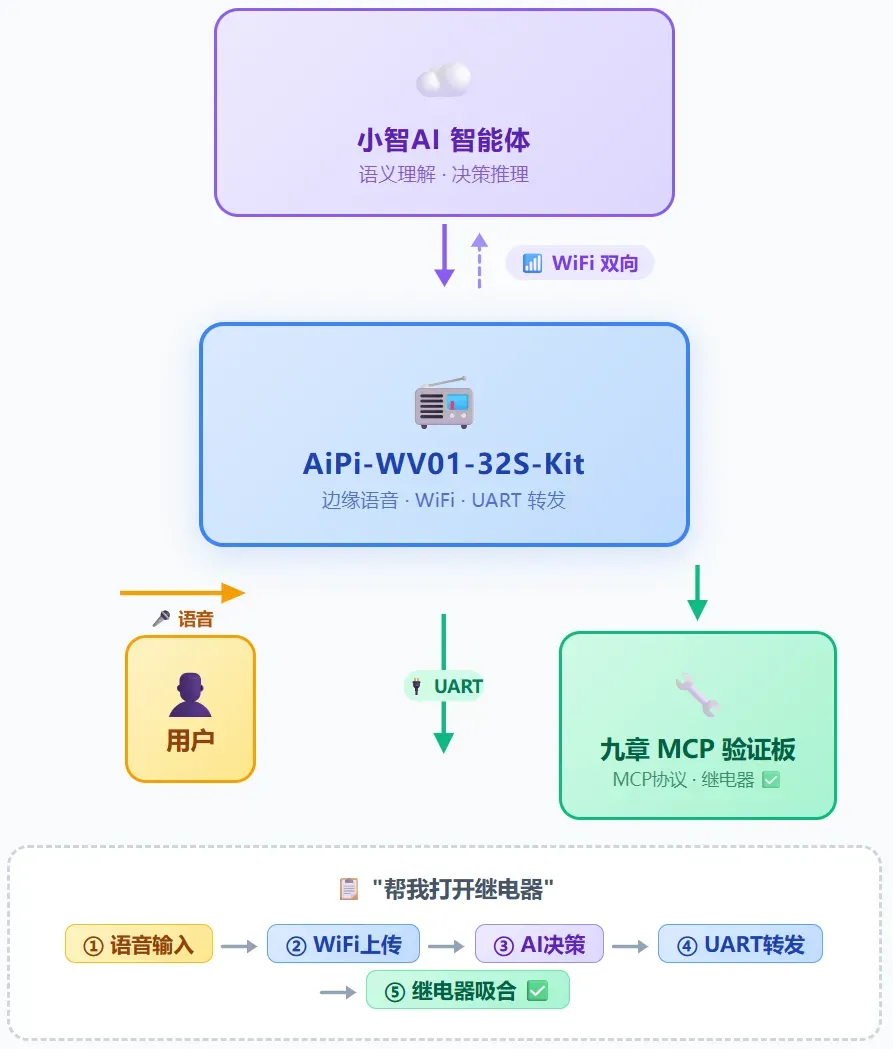
MCP Protocol Workflow Diagram
🎙️ Offline Voice Wake-up
Ai-WV01-32S-Kit supports offline voice wake-up, eliminating the need to press buttons for dialogue. Supports WeChat mini-program for network configuration and AI agent setup.
📦 Assembly Diagram
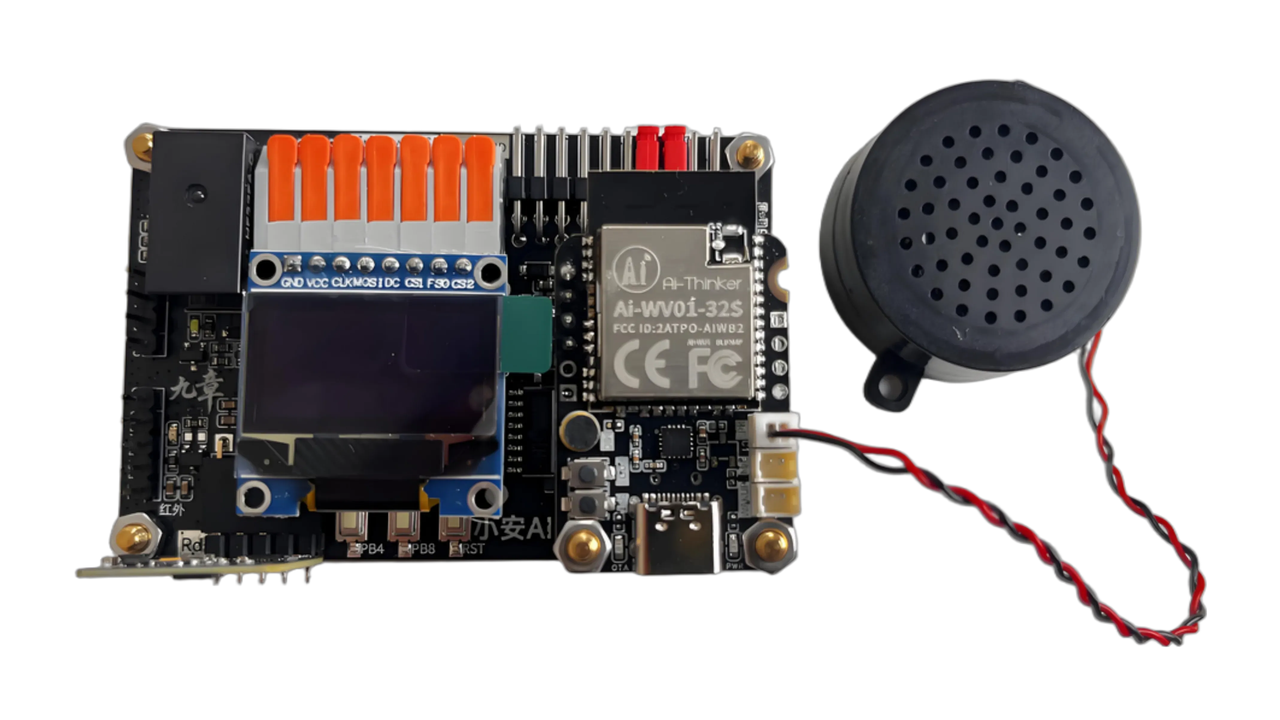
🔍 "9Mod" MCP Verification Kit · Assembly Overview
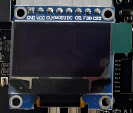
🖥️ OLED Module
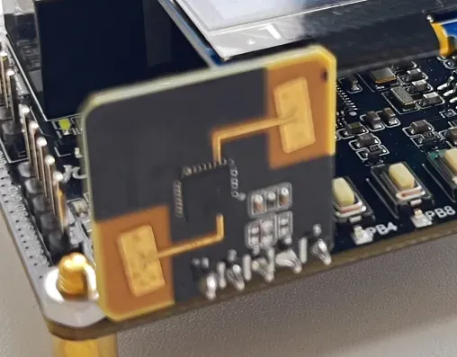
📡 Radar Detection Module
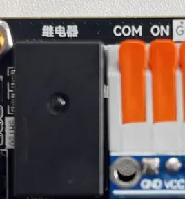
🔌 Relay Module
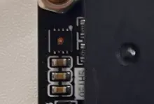
🌡️ Temp/Humidity Circuit
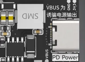
⚡ PD Decoy Circuit
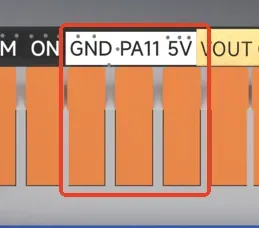
🌈 WS2812 Interface
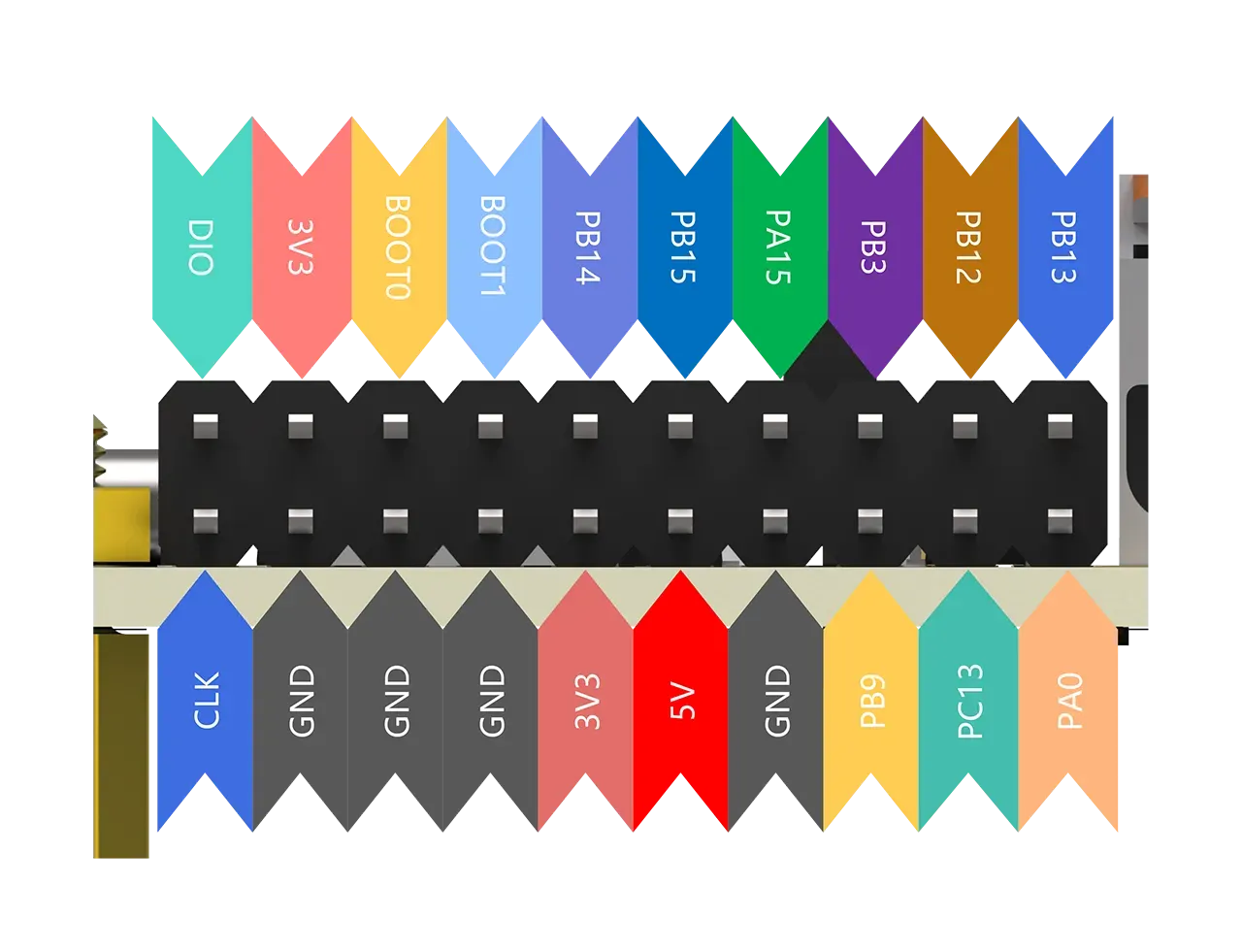
📍 GPIO Expansion
🔌 CH224K PD Decoy — I²C Address
The CH224K is a PD decoy chip from WCH (Nanjing Qinheng Microelectronics). It uses the I²C interface to configure the output voltage (5V/9V/12V/15V/20V). On this board, the CH224K shares the PB6/PB7 I²C bus with the SHT30 temperature/humidity sensor, distinguished by device address.
| Parameter | Description |
|---|---|
| Chip Model | CH224K |
| Interface | I²C (7-bit slave address 0x40) |
| SDA Pin | PB6 |
| SCL Pin | PB7 |
| Output Voltage | 5V / 9V / 12V / 15V / 20V |
| Max Output Current | 3A (depends on PD charger capability) |
🖥️ 0.96" OLED Display — SPI Pin Details
The onboard 0.96" OLED uses the SSD1306 driver IC (128×64 pixels) with SPI interface. An additional GT20L61S Chinese font chip shares the same SPI bus via an independent chip select (PB0).
Connector: OLED module connects to the mainboard via 2.54mm pin headers.
⚡ Power Parameters
| Parameter | Specification | Notes |
|---|---|---|
| Power Input | Type-C (PD Decoy) | CH224K decoys PD charger; can also power via TTL USB port |
| Input Voltage Range | 5V ~ 20V | Determined by PD profile; max rated DC 28V (TVS protected) |
| System Rated Current | <200mA @ 5V (no peripherals) | STM32F103CBT6 + OLED + SHT30 + base circuit |
| PD Decoy Output | Max 20V / 3A (60W) | Output to VBUS header, ⚠️ High voltage |
| 3.3V LDO | 3.3V / 800mA | Onboard LDO reglates to 3.3V for MCU and peripherals |
| WS2812 LED Strip Power | 5V / 2A Port | Independent power port, requires external 5V supply |
| Motor/Expansion Power | 9V~15V / 2A | Via expansion headers, with surge protection |
| Total Power Consumption | ≤ 1W (no external load) | Typical @5V/200mA |
📋 Certification Status
Product certification status (continuously updated as certification progresses):
| Certification | Status | Notes |
|---|---|---|
| 🔰 CE (EU) | Pending | Certification in progress, results will be updated upon completion |
| 🇺🇸 FCC (USA) | Pending | Certification in progress, results will be updated upon completion |
| 🇨🇳 SRRC (China) | Pending | (Required if wireless modules are involved) |
| 🌏 RoHS | Compliant | Compliant with RoHS Directive 2011/65/EU |